A car wheel meets the road through a rubber tire. Turn the steering wheel and the road wheels change direction; on a conventional driven axle, a differential lets the two sides rotate at different rates through a bend. A train wheel has a harder assignment. Its steel tread runs on the narrow head of a steel rail, and on a conventional wheelset the left and right wheels are fixed to the same axle. They turn together. The rails set the path, yet the outer rail in a curve is longer than the inner one. How can wheels with one rotation rate cover different distances without dragging their way round every bend?
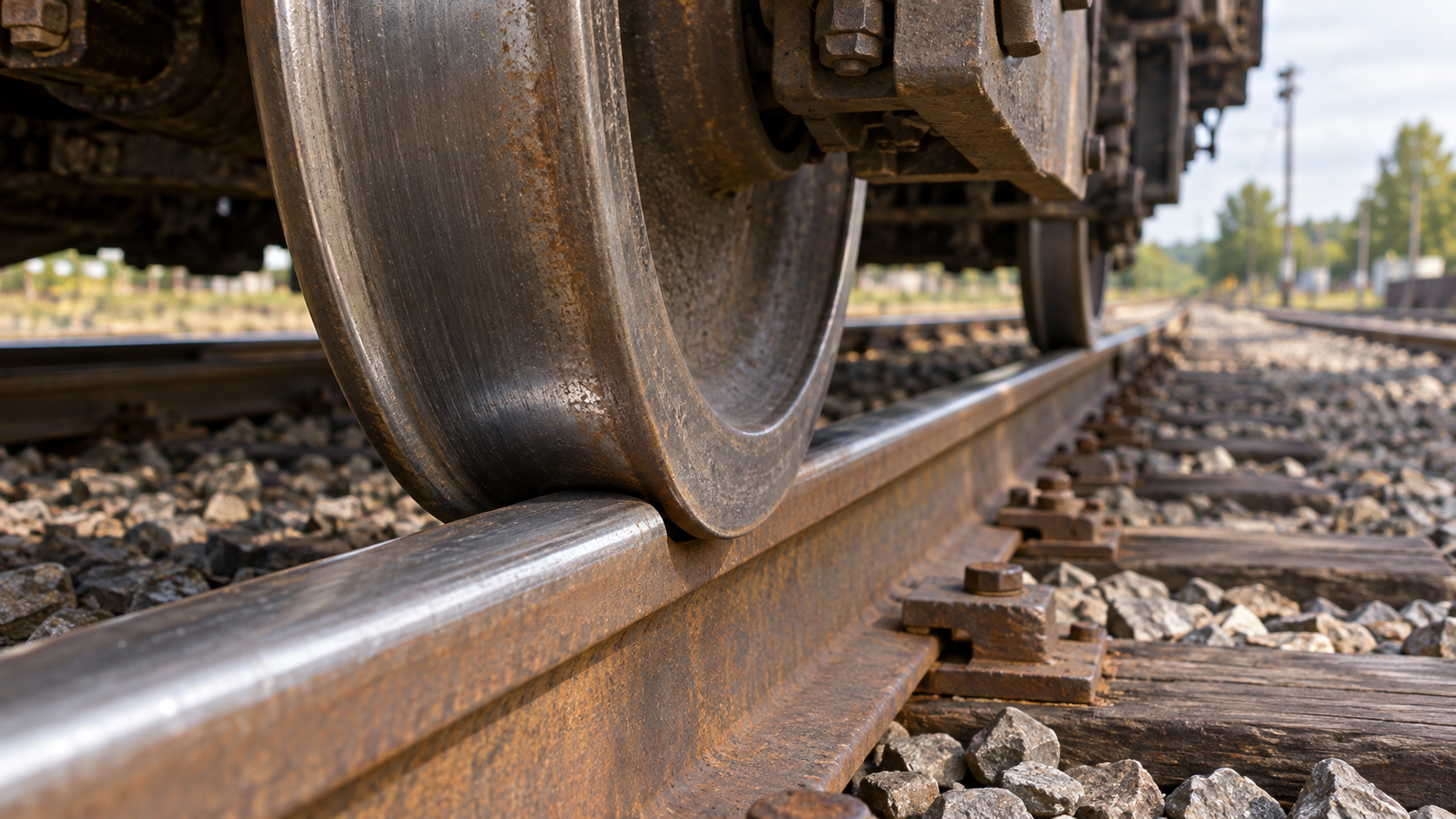
Part of the answer is visible if you look across the width of a railway wheel. The tread that bears on the rail is not simply a flat cylinder. Its profile changes the effective rolling radius as the contact point moves sideways. Near the inner side of the wheel is a raised flange, which can meet the rail's gauge face when lateral movement brings it there. The wheel, axle, rail head, and their clearances make a steering system together. The car comparison is useful because its steered road wheels and differential solve the turn in different ways; neither a driver's steering input nor a standard road-car differential explains the ordinary fixed railway wheelset.
One axle, two distances
Imagine a gentle curve. The wheel on the outside has farther to travel. If both wheels are rigidly connected, they complete the same number of revolutions. A larger effective radius at the outside contact point makes each of those revolutions cover more distance; a smaller radius at the inside contact point covers less. A sideways shift of a shaped wheelset on its rails can produce that difference. The Federal Railroad Administration's 2013 bogie study lays out this curve mechanism and its limit: on broad curves, the radius difference available from the profiles may permit nearly pure rolling; on tighter curves, it may not be enough. Then creep, slip, the wheelset's angle to the curve, and sometimes flange contact become more important. No amount of tidy cone drawing makes every curve a slip-free one.
The same shape helps explain what happens on straight track. If a conventional wheelset shifts sideways, the two contact points can move to parts of the treads with different rolling radii. Because the wheels are coupled, that difference tends to turn the axle back across the rails. In a simple ideal model, the wheelset weaves gently about the center rather than running continuously against one flange. The FRA's 1975 analytical and experimental study treats this rolling-radius response as a central part of lateral guidance, then measures how it changes with the actual wheel and rail shapes. The word tends matters: suspension, speed, track irregularities, friction, and wear affect the vehicle's real motion.
That is the job a cylindrical wheel would struggle to do on a fixed axle. Slide a perfect cylinder sideways on an ideal straight rail and its rolling radius stays the same. It gains no comparable radius difference to steer itself back or to make the two sides cover different curve lengths. The 1975 FRA study uses that idealization to show why relying on the flanges alone would change the guidance problem. Railway wheels are shaped so that tread contact can do useful work before a flange is pressed against a rail.
The flange is there for a reason
A flange is sometimes described as if it sits in a groove and steers the train at every moment. On ordinary straight running, the main load is carried where the tread bears on the top of the rail, and there is usually lateral room before a flange meets the side. The flange is not ornamental. When geometry, a tight curve, irregular track, or other forces use up that room, flange contact can constrain the wheelset's movement. The FRA's wheel–rail geometry experiments explicitly track the lateral position at which such contact begins. British track requirements also specify check rails on certain tight curves to manage high lateral forces and guide wheel flanges through the flangeway. That is a defined use of flange guidance, not proof that every wheel rides its flange all along the line.
It helps to separate support from guidance. The rounded top of the rail and the wheel tread carry vertical load through their contact area. The flange and gauge face provide a lateral boundary when they meet; the tread's changing rolling radius can guide the coupled axle without constant flange contact. These contacts are not perfectly pure rolling. Small relative motions, called creepage, generate forces that help a real wheelset steer, especially in curves. The simple radius picture explains why the geometry is helpful, while the full vehicle includes forces, suspension, and motion that a still photograph cannot show.
A profile belongs to a pair
“Cone” is a teaching word, not a universal wheel specification. Some railway treads include several curves and slopes; a worn tread may become hollow. Rails have their own head profiles and may be tilted inward. The useful quantity, often called equivalent conicity, describes how the rolling-radius difference changes as a particular wheelset moves laterally on a particular pair of rails. It is a property of that pairing and its state of wear, not a number stamped permanently into a wheel. A 2002 FRA study of hollow-worn North American freight wheels plots rolling-radius difference against lateral shift for several wheel and rail combinations. The report finds that detailed wheel and rail profiles, differences between the two wheel radii, flange wear, and track gauge all affect the result. It does not reduce behavior to the tread's nominal taper.
Too much of the wrong response can be troublesome as well. A wheelset may oscillate from side to side, a motion railway engineers call hunting. The 2002 FRA report found that hollow wear could lower the onset speed of instability in the tested freight-vehicle combinations, while stressing that wear alone was not the whole explanation. More taper is therefore not simply “more steering” and a better wheel. Curve negotiation and stable running at speed place competing demands on the wheelset, rail, and vehicle suspension.
The rail is maintained with this pairing in mind. Britain's 2023 track-system standard specifies rail-head profiles and a nominal inward inclination for its main-line plain track, linking those choices to compatible wheel profiles, curving, and stability. Those are Great Britain requirements, not a worldwide rail angle. An earlier FRA and Association of American Railroads track experiment tested specially ground rail-head shapes against a selected wheel profile and measured changes in wheel–rail forces and wear. Grinding the rail can change the relationship just as changing a wheel profile can.
So the distinctive train wheel is not explained by the flange alone, nor by a perfect cone. It is a shaped steel tread working with a shaped rail beneath a coupled axle. On a broad bend, a shift in contact points can give the outside wheel the larger rolling path it needs. On straight track, the same changing radii help the axle find its course, within the limits set by speed, wear, and suspension. When those limits are reached, the flange and the rest of the running gear become unmistakable parts of the story.
A thought worth keeping?